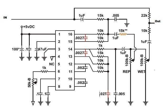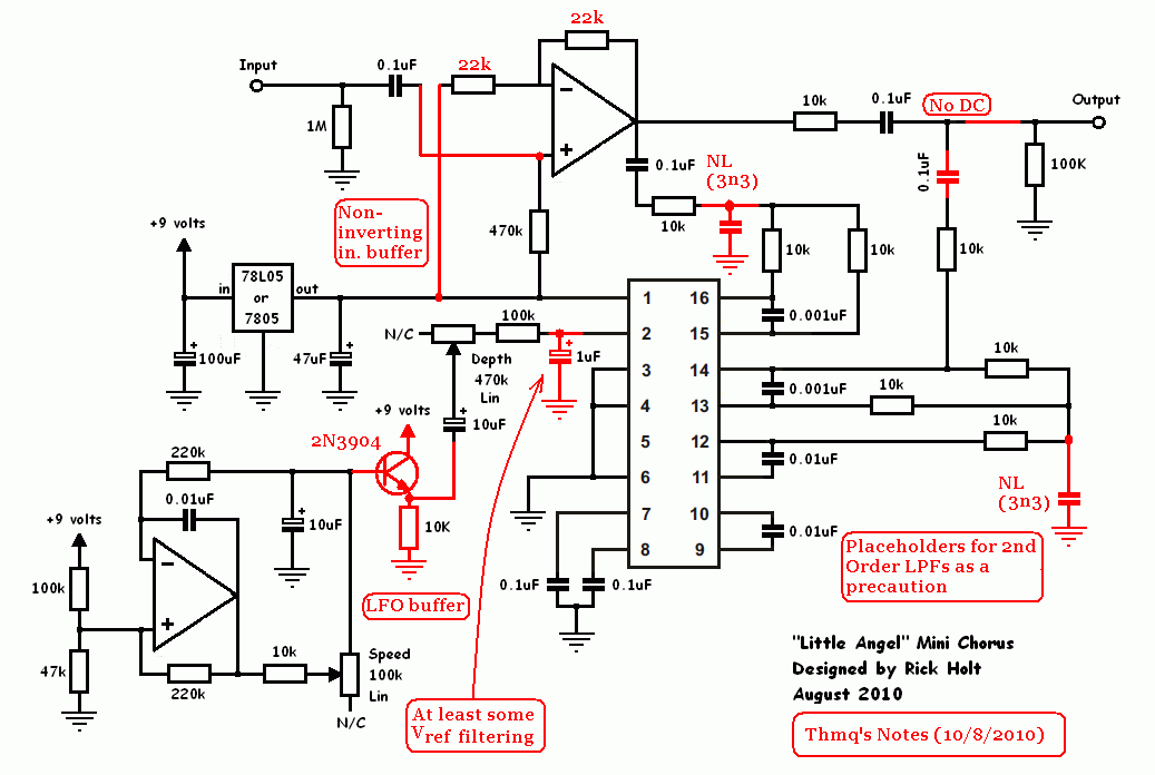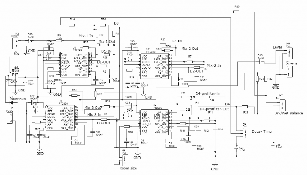

Yes all those symbols are for me - I probably should have posted a more generic schematic. Any help on this will be deeply appreciated! I see some of them are probably there instead of "wires" connecting different parts of the circuit since they have the same name (despite the fact that they are not on a bus or something) but others are simply there not pointing to anything. Thank you for providing your help and answering some of my questions but I could use some more help as I don't I have a clue to all the abbreviations on the schematic and what they mean. If your documentation and/or schematic does not allow this, there is something wrong (and you fail the class ) it is obvious when you put up all this effort to put together the circuit, troubleshoot it, optimize it, and finally publish the schematic and and a result (sound file) from it!!!īut why do all this in a way that makes people asking you questions just to figure it out? My teachers used to say that a schematic, a few pages of documentation and in some cases a mechanical drawing and a layout (for RF, etc) should be all that you need to build an analog circuit. I had to learn electronics from some very "bitchy" teachers and apparently they gave me their attitude (it's true what I said about failing you without a second thought.). It was frustrating as you can imagine :grr Once more, I have to apologize for my complete lack of diplomacy but I got excited when I saw the posting and immediately crashed when I saw a schematic I could not "read" immediately and figure out what is happening. Sorry for not being more "diplomatic" as you said. The regulator for example draws less standby current, allows for a smaller drop for regulation and I beleive has a better transient response than a 7805. Seriously though if you have questions I will answer them and lets leave it at that.Ī number of parts are arbitrary choices based on what I had floating around others matter. You can just mark them out - if they confuse you?Ī number of people have built this "unintelligble" circuit with no problem and have conveyed to me excellent performance - so I am sure you and your professors can figure it out too All of the symbols are referenced to the various jacks and switches at the pedal level.

It difficult to tell where to draw the line with detail so I figure anyone who actually wants to try to build or experiment with the circuit - will put forth the effort to reach out. Lots of people have emailed or posted with questions and I have happily answered them. I am smart enough to refine my formatting and style- when someone gives defacto feedback by asking questions. You could just say your having some trouble reading my schematic and ask me to clarify. I think you could be a little more diplomatic with your post This is the main reason, we all share the same notation: collaboration!!! If you clear this schematic up, I would be the first to jump in, play with it and give some feedback on it. This is why we all use the same symbols for resistors ,capacitors, transistors, etc.
#PT2399 SIMPLE DELAY SCHEMATIC HOW TO#
This is why there are rules out there on how to design a schematic. When you take the big decision to publish it even on a forum you must make sure it is clear and helpful to everybody. I am not trying to be judgmental or anything, just trying to say that a schematic that is clear as day to you might be clear as mud to others. Great work but if you had my Electronics professors in college, they would fail you without a second thought. If there is a reason for the substitution it must be documented. Same goes for the MCP1804T, why this device to regulate 9V to 5V when a generic 7805 would do the same.

Is BAS16LT3G really necessary or a 1N4148 would do in its place? When you introduce specific components it is good to explain why you need the extra 200mV forward voltage and low leakage current of the specific device over the "generic" type. Where is the opamp (LP2, shouldn't it be U*?) between pins 13 and 14? It is always good to explain what you mean when you introduce abbreviations. I would really, really love to play with this circuit but the schematic is unintelligible. I absolutely loved what I heard but puzzled by what I saw. I have a noise problem with my pt2399 circuits (doesn't everybody?) and I learned to live with it, until I saw this posting (a little late I have to admit). Attracted by the PT2399 noise problem improvement I saw.


 0 kommentar(er)
